Ladder Logic Of Xor Gate. Web so, now let's start implementing some complex logical gates in ladder logic for plc. The or gate gives an output when either or both of the inputs are 1. Web plc exclusive or (xor) logic. The below figure shows the plc ladder logic of the or gate, which shows the output coil turns “on” when any one of the inputs will be on. When input a and input b are not activated then there is 0 output. Y = a + b. Web there are seven basic logic gates which are: Web or logic gate is the basic addition logic gate. Web figure 11 shows a ladder diagram for an xor gate system. 12k views 2 years ago #logicgate #plc #omronplc. Sometimes there is, however, a need for a gate that gives an output when either of the inputs is 1 but not when both are 1, i.e., has the truth table: Web the xor gate takes two inputs and produces an output depending on the combination of the two inputs applied. Such a gate is called an exclusive or or xor gate. “and”, “or”, “not”, “nand”, “nor”, “xor”, and “xnor”. Today, we are gonna implement.
from cartoondealer.com
Web there are seven basic logic gates which are: Web or logic gate is the basic addition logic gate. Web so, now let's start implementing some complex logical gates in ladder logic for plc. Y = a + b. The output will turn on if any of the inputs will be on. “and”, “or”, “not”, “nand”, “nor”, “xor”, and “xnor”. Such a gate is called an exclusive or or xor gate. When input a and input b are not activated then there is 0 output. Today, we are gonna implement. The or gate gives an output when either or both of the inputs are 1.
Digital Logic Gate XOR Gate. Electronic Symbol. Illustration Of Basic
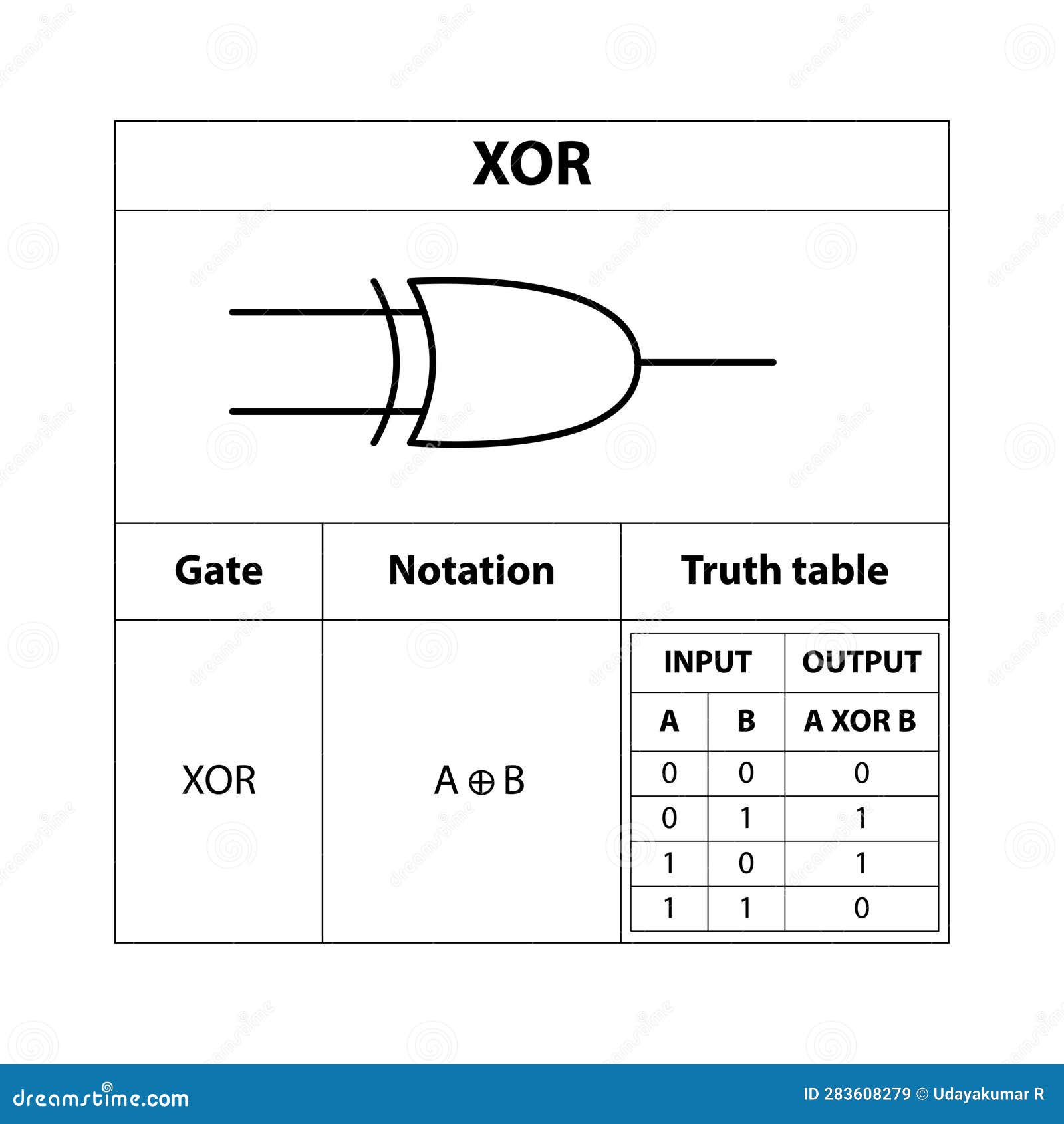
Ladder Logic Of Xor Gate When input a and input b are not activated then there is 0 output. Web figure 11 shows a ladder diagram for an xor gate system. Web or logic gate is the basic addition logic gate. Y = a + b. The or gate gives an output when either or both of the inputs are 1. “and”, “or”, “not”, “nand”, “nor”, “xor”, and “xnor”. When input a and input b are not activated then there is 0 output. Plc ladder logic of or gate. Web so, now let's start implementing some complex logical gates in ladder logic for plc. Sometimes there is, however, a need for a gate that gives an output when either of the inputs is 1 but not when both are 1, i.e., has the truth table: Such a gate is called an exclusive or or xor gate. Web plc exclusive or (xor) logic. Today, we are gonna implement. Web the xor gate takes two inputs and produces an output depending on the combination of the two inputs applied. The below figure shows the plc ladder logic of the or gate, which shows the output coil turns “on” when any one of the inputs will be on. Web there are seven basic logic gates which are: